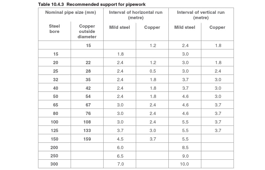
Span Pipe Support Spacing Table Standards
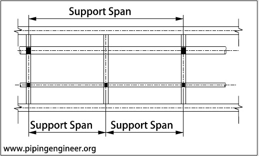
Piping Support Span The Piping Engineering World

Hanger Support Spacing Rod Sizes Horizontal Pipes

Truss Span Table Png 1000 499 Roof Trusses Flooring Wood Roof

Blog Little P Eng For Engineers Training Engineering Services

Minimum Pipe Spacing In Pipe Rack The Process Piping
Pipe Expansion And Support Spirax Sarco

2 7 0 2143 2 6 9 25 1622 3 7 10 0 1500 4 8 10 0 1500 5 calculated 11 0 1364 figure 2.
Span pipe support spacing table standards.

Allowable Pipe Support Span Calculation

Chapter 12 Fuel Gas Piping California Plumbing Code 2016 Upcodes

Load Tables For Unistrut P1000 P1001 Unistrut Service Co
Https Beacomp Com Wp Content Uploads 2018 01 Support Tech Paper Word Pdf

Multi Function Work Bench Workbench Festool Festool Tools

Pin On Carpentry
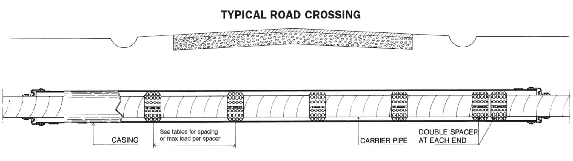
Specifications Raci Spacers

Everything You Need To Know About Picking A Roofing Company Spray Booth Roof Repair Diy Roof Repair

Practical Process Plant Layout And Piping Design

Pin On Shelves

Pin On Interior

Circular Section Reinforced Concrete Column Details Reinforced Concrete Concrete Column Concrete Retaining Walls

Farmhouse Table Leg Template Wood Turning Wood Lathe Diy Table Legs

Live Edge Cedar Industrial Computer Desk Diy Industrial Lighting Industrial Computer Desk Industrial Lighting Design

Spacing Of Pipe Supports Enggcyclopedia

Industrial Reclaimed Barn Wood Sofa Table Etsy Table Decor Living Room Wood Sofa Table Reclaimed Barn Wood

Pin On Garage Storage Ideas Diy Garage Organization

Carpenters Wall Bracket Google Search Staging Plank Building A House
Https Encrypted Tbn0 Gstatic Com Images Q Tbn 3aand9gcqnz1gbrdtkgugp3jlo Avwco47ep0cd4yh4 D Aq6bea8o V5u Usqp Cau

Pin On Pipe Tables

Simple Steamer For Bending Wood Strips By Donnie Fauber Drill 3 16 In Dia Through Holes 5 In Ap How To Bend Wood Steam Bending Wood Woodworking Joints

Pin On Diy

Pin On Capitol Romance Wedding Love
Pin On Myprojects
Source : pinterest.com
