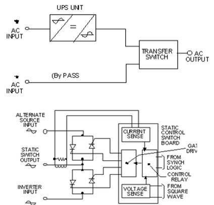
Static Switch Circuit Diagram
Static Transfer Switch

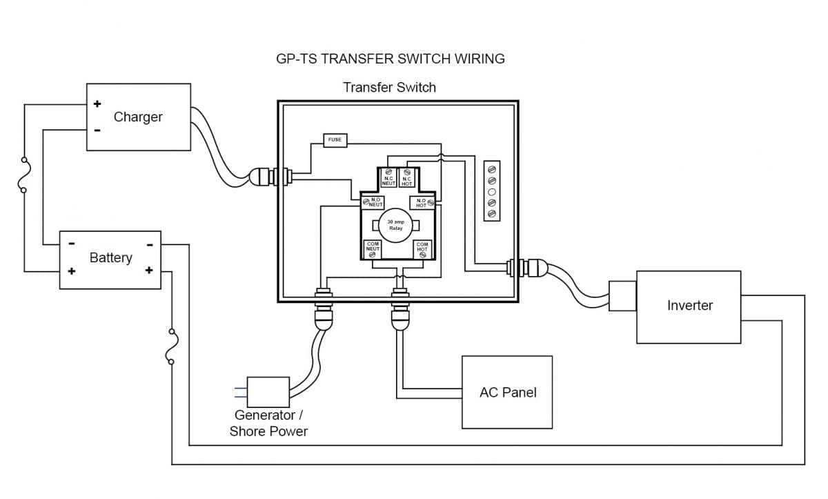
Generator Transfer Switch Wiring Diagram Generator Transfer Switch Transfer Switch Solar Energy Information

Image Result For Generator Transfer Switch Wiring Generator Transfer Switch Transfer Switch Generation

Image Result For Generator Transfer Switch Wiring Transfer Switch Generator Transfer Switch Electrical Circuit Diagram
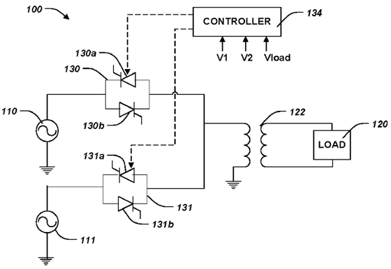
Pinnacle Static Transfer Switch

Manual Changeover Switch Wiring Diagram For Portable Generator Transfer Switch Generator Transfer Switch Outlet Wiring

Capable of providing all information concerning equipment operation status.
Static switch circuit diagram.

How To Wire Ups Inverter With Automatic Changeover Switch Transfer Switch Electrical Diagram Switch

Automatic Transferred Switch Ats Circuit Diagram Electrical Engineering Blog Transfer Switch Circuit Diagram Electrical Wiring Diagram

Wiring Riddle No 3 Auto Transfer Switching Diagram Teknik Listrik Teknik Listrik

Gentran Transfer Switch Wiring Diagrams Transfer Switch Generator Transfer Switch Switch

Manual Changeover Switch Wiring Diagram For Portable Generator Or How To Connect A Generator To House W Transfer Switch Generator Transfer Switch Outlet Wiring

Pin By Denis Pu On Groupe Electrogene In 2020 Portable Generator Transfer Switch Home Electrical Wiring

Typical Automatic Transfer Switch Block Diagram Find More About Automatic Transfer Switch On Http Yout Generator Transfer Switch Transfer Switch Generation

Generator Changeover Switch Wiring Diagram As Well As Solar Transfer Switch Generator Transfer Switch Electrical Projects

Circuit Diagram Of Automatic Tranfer Switch Transfer Switch Pic Microcontroller Microcontrollers

Thyristor Circuit And Thyristor Switching Circuits

Image Result For 3 Phase Changeover Switch Wiring Diagram Transfer Switch Circuit Diagram Electrical Wiring Diagram

Wiring Riddle No 3 Auto Transfer Switching Control Diagram Automatic Transfer Switch At Transfer Switch Electrical Circuit Diagram Generator Transfer Switch

Generator Transfer Switch Wiring Google Search Generator Transfer Switch Transfer Switch Electrical Projects
Automatic Transfer Switch Switch Between Solar Generator And Main Grid Power Ats Diy Tech Repairs

Automatic Transfer Switch Single Line Diagram Representation Single Line Diagram Line Diagram Transfer Switch

Automatic Transfer Switch Switch Between Solar Generator And Main Grid Power Ats Diy Tech Repairs Transfer Switch Electrical Circuit Diagram Switch
Https Www Powersystemsinternational Com Wp Content Uploads 2017 02 Static Transfer Switches 2017 Pdf
Automatic Transfer Switches Mobile Solar Power Made Easy
Https Encrypted Tbn0 Gstatic Com Images Q Tbn 3aand9gcr17 Ble5wxj3xskphuxcf3ouol5y3hs1yeu Cksjjsuaz0y4tf Usqp Cau

Electrical Wiring Be28 Automatic Transfer Switch Controller Connections Diagra Diagrams Electrical Circuit Diagram Transfer Switch Electrical Wiring Diagram
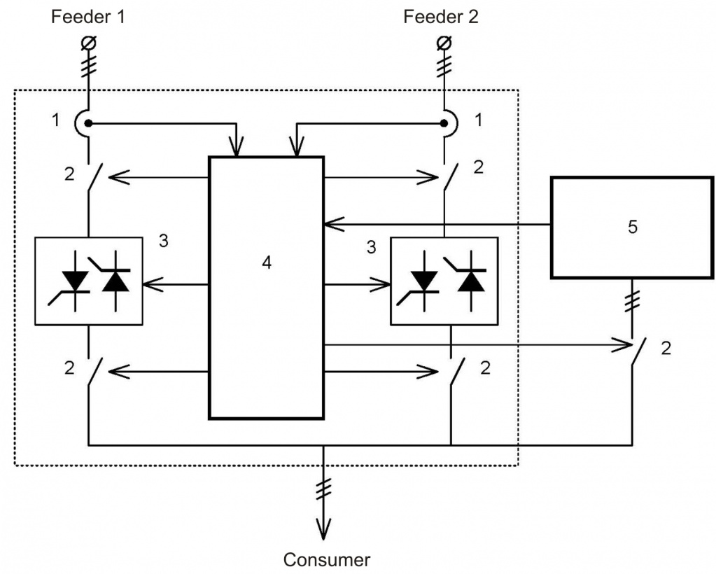
Low Voltage Installation Static Transfer Switch Sts

Generac Manual Transfer Switch Wiring Diagram Transfer Switch Generator Transfer Switch Switch

Gentran Vinatage Models Manual Transfer Switch Wiring Diagram 1 Gif 450 439 Electricidad Electrica Electronica

Diagrama De Cableado Cableado De Un Generador Portatil A Casa Manual Del Diagrama De Cableado Del Transfer Switch Portable Generator Generator Transfer Switch
Source : pinterest.com
